Speaker Protection Circuit Diagram
C1237ha is a monolithic integrated circuit designed for protecting stereo power amplifier and loudspeaker. This is done in order to ensure that the dc blocking capacitor at the amplifier's output is charged before it is connected to the speaker.
Speaker protection circuit
There are no products to list in this category.

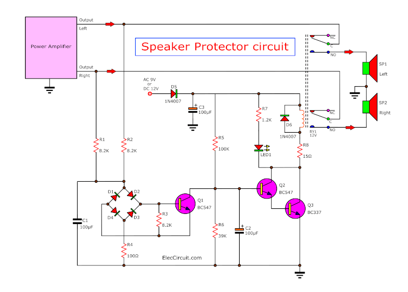
Speaker protection circuit diagram. The speaker protection circuit requires an auxiliary voltage to be provided from a winding of the mains transformer, the value of this voltage should be between 9v ac to 12v ac. 0 320 less than a minute. An important feature of an audio amplifier is to provide a system to protect your speakers in case the amplifier breaks down and puts dc on the speaker terminals.
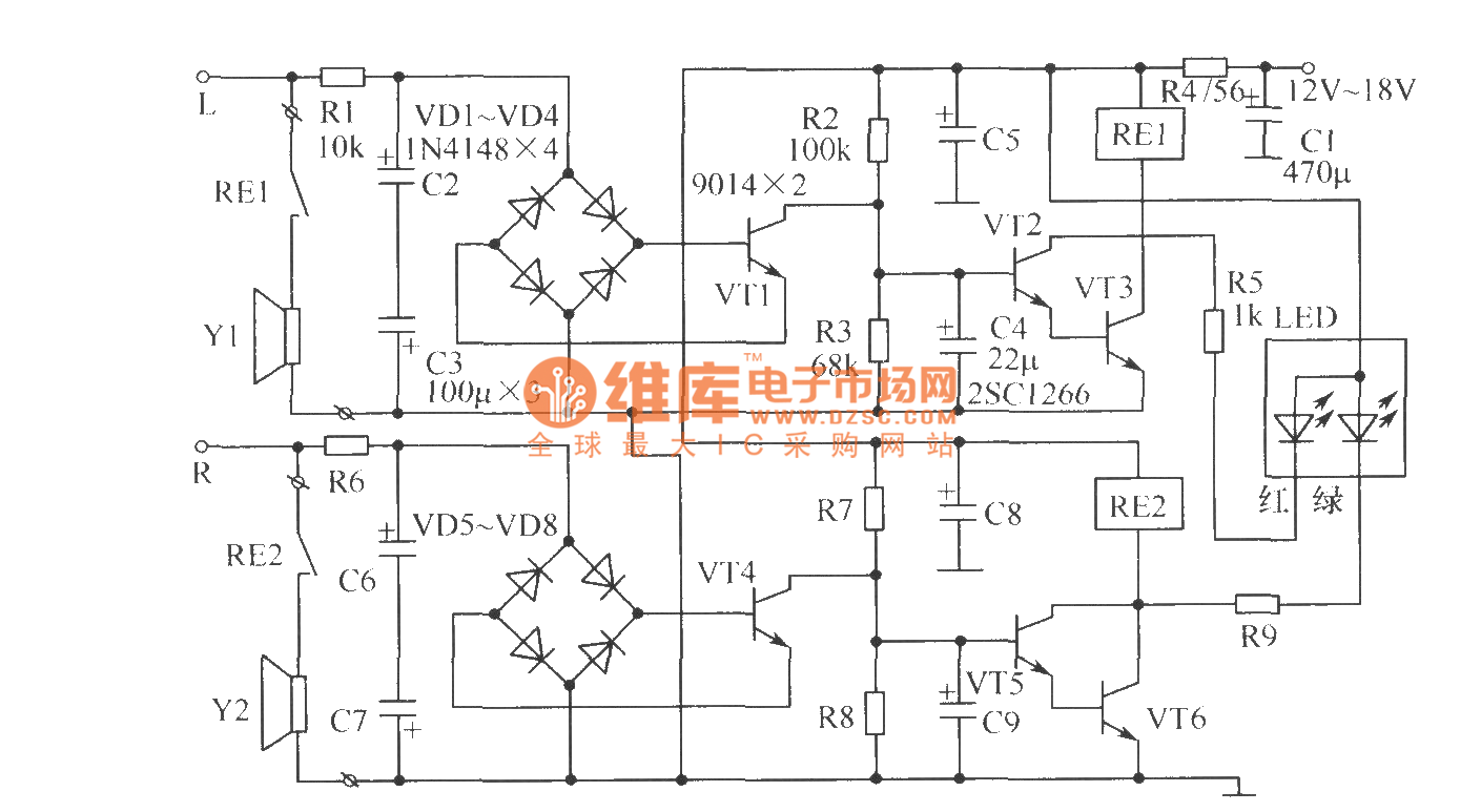
When high current is drawn from the power supply, the speaker connection is cut off, and the dc voltage generated at the output of the amplifier is disconnected in the same way. These devices are to be applied directly to audio power amplifiers, one of which is installed in the majority of speaker systems. As shown in the circuit, the signal from the speakers enter through resistors r1 and r2 into the protection speakers section.
It automatically connects power when the temperature returns to normal. The drawing above shows how the circuit is wired into an amplifier. We connected it to the in of the protection speaker to both the left and right.
If amplifier got any problem then this circuit protect. The e + section will be connected to the equalization resistor of the transistor (2sc5200 or irfp240) from the positive supply stage. The loudspeaker protection circuit for transistor amps is a different development of the " delayed and loud speaker dc protection circuit " application i have previously shared.
To protect the loudspeakers in the unlikely event of an amplifier power stage failure, where dc component would damage the speaker voic coil. Connect the ground wire from the amplifier to the ground of the protection speaker. Then, connect the signal output from the amplifier to the speakers.
The circuit diagram is not very clear for the connection below, see the sample diagram about the amp, dc protection connection. Protection circuits have been designed to prevent this kind of damage, and come in many flavors. Please kindly assist me to like share an.
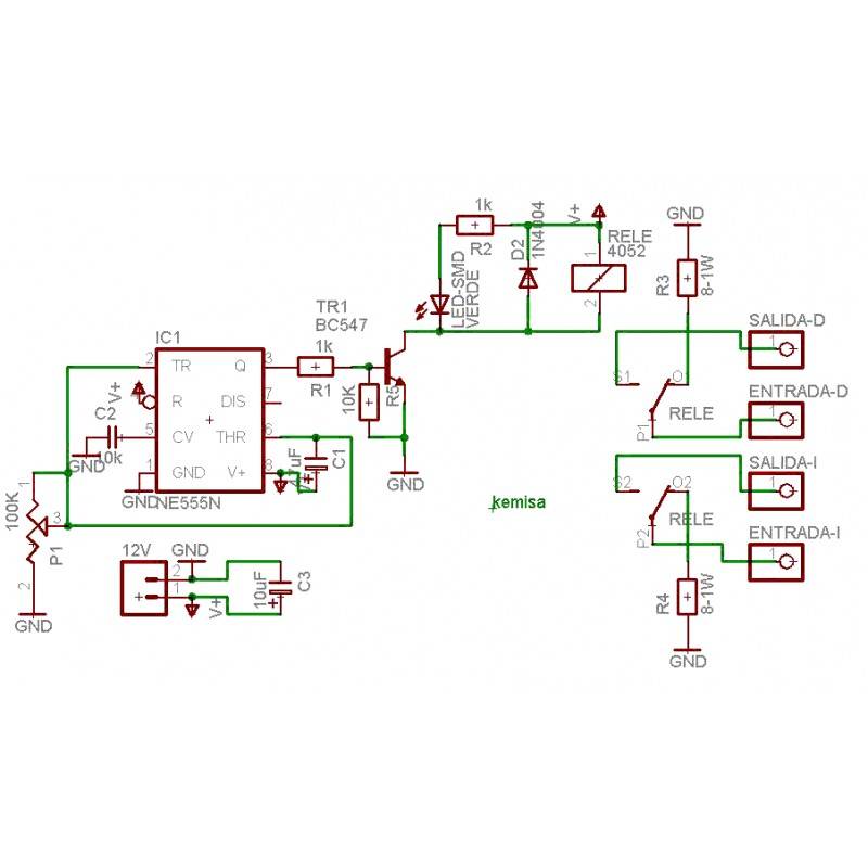
Work stably within a wide power supply voltage range. Package/case 8 pin plastic slim sip. The given amplifier short/overload protection circuit diagram, shows an inexpensive design using just a single transistor for implementing the intended feature.
There will usually be a separate relay for each channel, and the p33 board will often be able to use the main amplifier power supply as shown. For higher voltage values, some components from the speaker protection circuit board need to be replaced. In addition, the frequency response of the circuit is way better than the other circuits available.
No speaker will take kindly to the presence of 50v on its voice coil, so that has to be prevented. This power supply circuit is equipped with an advanced protection system. (vcc = 25 to 60v) contain a relay driver.
It's protect our speaker from any short circuit. The picture of the speaker protection. Complex speaker protection circuit schematic circuit diagram.
Amfide how many en have, in parallel. This circuit will cut off the power to the amplifier board at the moment it senses a high temperature. Speaker short circuit protection circuit diagram and pcb drawing.
The circuit uses an ntc thermister as heat sensor. Wiring of protection circuit and amplifier. Now you can protect your hifi amplifier from damage due to excess heat.
Most speakers burn out or are mechanically damaged by this very quickly. Normally a low value resistor is usually employed at the output of mosfet amplifiers, the current developed across this resistor can be well exploited for tripping a relay in case it exceeds the safe. If an auxiliary supply is used, it needs to be around 12v to suit the relay coils.
The presented amplifier short/overload protection circuit diagram, demonstrates a cheap design utilizing just a single transistor for applying the meant feature. Next, connect the out signal from the speaker to the positive terminal of the protection speaker. The device uses power amplifiers, full bridge rectifiers and npn transistors to effectively support the speakers.
During this initial delay period the output of amplifier will be grounded by the resistor r2 through the n/c contact of the relay. Usually a low value resistor is normally used at the output of mosfet amplifiers, the current designed across this resistor could be well used for tripping a relay just in case it surpasses the safe highest current. This circuit uses center tap transformer and the power supply circuit design already provided in the schematic diagram.
Relay and mosfet speaker protection. Protection circuit for both left and right channels. Features of the speaker protection circuit;
This is the speaker protection circuit diagram.

Pin on speakers

Pin on Amplifier

300W Subwoofer Protection DIY Electronics Projects
Speaker Protection Circuit Diagram Power Amplifier 500W

DC Protection for Speakers Schematic Circuit Diagram

Overload Speaker Protection Circuit Diagram Electronic

DIYfan Speaker protection with uPC1237

DC speaker protection circuit explained Part I ALPHA Lab
Speaker Protection Circuit


AMPLIFIER POWER SUPPLY AND PROTECTION CIRCUITS Schematic
![]()
Stereo Speaker Protection Electronic Circuit

Pin on Bsw

COMPLEX SPEAKER PROTECTION CIRCUIT SCHEMATIC CIRCUIT DIAGRAM
DIYfan Speaker protection with uPC1237
Other Audio Related Projects BuildAudioAmps
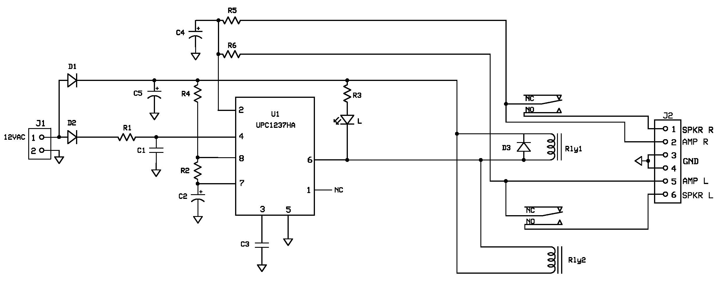
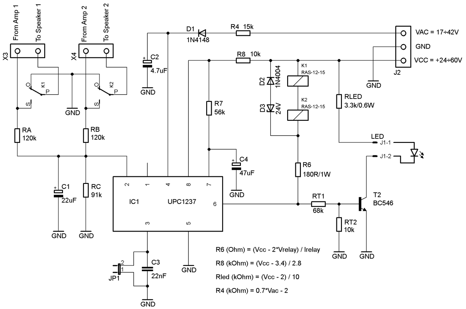
DIYfan Speaker protection with uPC1237
The tweeter speaker protection circuit

Power Amplifier 500W with Speaker Protection Electronic
Speaker protection circuit Protection_Circuit Control